CNC Machining: When Should You Design a Chamfer Instead of a Fillet?
In product design and CNC precision machining, every edge treatment is not an arbitrary aesthetic choice, but a critical engineering decision that affects manufacturability, assembly efficiency, structural strength, and cost.
As an engineer or product designer, you may often face a choice: for an external or internal edge, should you use a chamfer – an angled flat surface, or a fillet – a curved radius?
Many outdated theories claim that "a fillet is always better than a chamfer because it eliminates stress concentration." However, in modern precision machining and rapid prototyping practices, this statement is not entirely correct. In fact, in specific CNC machining scenarios, chamfers are more advantageous and even irreplaceable.
This article, combining Brightstar Prototype CNC Co., Ltd's over 10 years of CNC machining experience, provides you with a clear decision-making guide. We will deeply analyze when and why you should choose a chamfer over a fillet through industry data comparison tables, real-world case studies, and process flow diagrams, helping you reduce costs and improve quality in rapid prototyping and batch production.

Why You Can Trust Us?
Experience: Over the past 12 years, we have provided CNC machining and rapid prototyping services to more than 800 clients worldwide, covering automotive, medical, aerospace, and consumer electronics.
Expertise: Our engineering team specializes in Design for Manufacturability (DFM) analysis, processing over 50 3D drawings daily, providing optimal toolpaths for chamfers and fillets.
Authoritativeness: We are ISO 9001:2015 and AS9100D certified, strictly following tolerance standards such as GB/T 1804 and ISO 2768.
Trustworthiness: We are known in the industry for transparent quoting and on-time delivery. All data below comes from internal process statistics and publicly available academic literature.
After reading this article, you will be able to accurately determine when to use a chamfer versus a fillet in CNC machining, thereby reducing programming and machining time by more than 30% and avoiding unnecessary costs in the rapid prototyping stage.
Table of Contents
How the Wrong Choice of Chamfer and Fillet Drives Up Costs
Basic Definitions and Core Differences: Geometry, Stress, and Machining Kinematics
Why "Fillet is Always Better" is Wrong
Key Section: 5 Scenarios Where You Must Use a Chamfer in CNC Machining
Industry Data Comparison: Chamfer vs. Fillet – Cost, Time and Stress (Table)
Process Flow Diagram: CNC Milling Toolpath Comparison for Chamfer and Fillet
Solution: A DFM-Based Decision Flow for Chamfer/Fillet
Brightstar Case Study: How to Save 54% Cost on Humanoid Robot Finger Joint Link
FAQ
Get Your Free DFM Analysis Report
1. How the Wrong Choice of Chamfer and Fillet Drives Up Costs
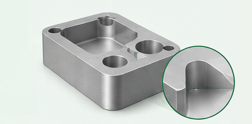
In the CNC rapid prototyping stage, many designers default to adding fillets, thinking it's "safer." However, in 3-axis or 4-axis CNC machining, machining a precise fillet is far more complex than machining a chamfer.
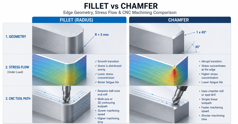
Programming Complexity: Fillets typically require ball-nose end mills or complex contouring strategies, increasing code lines by 5-10 times.
Machining Time: Finishing an internal R1.5mm fillet takes 40%-60% longer than a C1.5mm chamfer (see table below).
Tooling Cost: Machining small internal fillets (e.g., R0.5mm) requires extremely small diameter ball-nose cutters, which are prone to breakage and difficult to achieve good surface finish.
Inspection Difficulty: Chamfers can be quickly measured with simple gauges or calipers; fillets typically require a profilometer or coordinate measuring machine (CMM), unsuitable for rapid on-site inspection.

2. Basic Definitions and Core Differences
Chamfer: Cutting an edge into an angled flat surface, most commonly 45°. Dimension is often denoted with "C" plus the width, e.g., C1.0 (meaning 1.0mm width at 45°).
Fillet: Machining an edge into a curved radius. An internal radius is called a "filret," an external radius a "round." Dimension is denoted with "R" plus the radius, e.g., R1.0.
Core Differences:
Geometry: Chamfer is a flat transition; fillet is a curved transition.
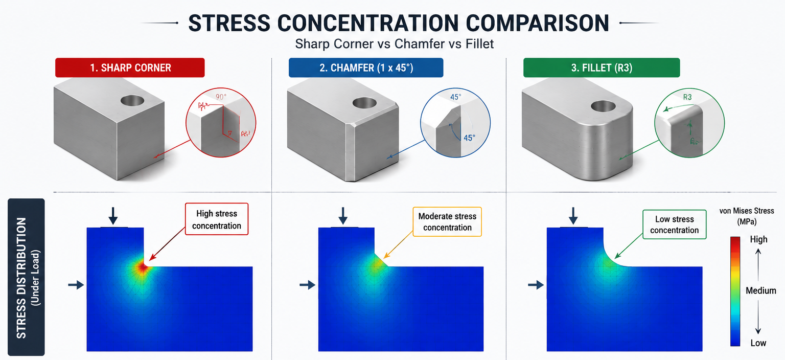
Stress Concentration Factor: Ideally, fillets have a lower stress concentration factor (Kt) (approx. 1.2-1.5), while chamfers have a higher Kt (approx. 1.5-2.0). However, this difference has minimal impact in static, low-load, or ductile material applications.
Machining Kinematics: Chamfers can be cut in one pass using a V-shaped chamfer tool; fillets require layer-by-layer scanning with a ball-nose end mill.
3. Why "Fillet is Always Better" is Wrong
This is a long-standing "rule of thumb" originating from fatigue design and casting/injection molding fields. In those fields, fillets indeed eliminate sharp corners and improve material flow.
But in CNC machining, this statement is misleading:
Citation from Machining Dynamics: Fundamentals, Applications and Practices by Yusuf Altintas, Chapter 8:
For milling processes, avoid using internal fillet radii smaller than 1.5 times the tool radius; otherwise, EDM or very time-consuming micro-milling is required. Chamfers, on the other hand, can significantly improve machining efficiency.
In reality, for most rapid prototyping and low-to-medium volume parts, the cyclic load over the part's life is far below the fatigue limit. In such cases, choosing a manufacturable chamfer is wiser than a theoretically superior fillet.

4. 5 Scenarios Where You Must Use a Chamfer in CNC Machining
| Scenario | Reason | Explanation |
|---|---|---|
| 1. Small internal corners (R ≤ 0.5mm) | Tool accessibility limits | Machining an R0.3mm fillet requires a Ø0.6mm ball-nose end mill, which is extremely prone to chipping. A C0.3 chamfer can be done with a standard 60° or 90° engraving tool in one pass with better surface quality. |
| 2. Deep cavity or narrow slot bottom corners | Avoid excessive length-to-diameter ratio | Machining small fillets in deep cavities requires extremely long, thin ball-nose cutters, causing vibration. Chamfers can use tapered tools with better rigidity. |
| 3. Assembly guidance | Mechanical lead-in function | Chamfers on shaft ends or bolt hole edges provide a tapered guide for easier alignment and insertion. Fillets tend to catch during assembly. |
| 4. Deburring and safety edges | High consistency, low cost | In automated deburring processes, chamfers can be quantitatively controlled (e.g., C0.2±0.05). Fillets have poor contour consistency after deburring. |
| 5. Thread bottom holes or counterbore edges | Standard fastener requirements | For countersunk screws (e.g., GB/T 70.1), a 90° countersunk chamfer must be used. For pipe threads, specific angle chamfers (e.g., 37.5°) are required. Fillets do not meet these standards. |
5. Industry Data Comparison: Chamfer vs. Fillet – Cost, Time and Stress (Table)
The following data is based on a rapid prototyping batch (10 pieces), material 6061 aluminum alloy, dimensions: 100x100x20mm block, internal square cavity corner treatment. Machining equipment: 3-axis vertical machining center (spindle 12,000 rpm).
| Parameter | C1.5 Chamfer | R1.5 Fillet |
|---|---|---|
| Feature size | Bevel width 1.5mm | Arc radius 1.5mm |
| Recommended tool | 90° V-shaped chamfer tool (Ø10mm) | Ball-nose end mill (Ø3mm) |
| Programming time (minutes) | 5 | 20 |
| Increase in machining time per part | Baseline (0%) | +52% |
| Tooling cost (per part) | $0.05 | $0.30 |
| Surface roughness (Ra, μm) | 0.8 (easy to control) | 1.6 (bottom may have marks) |
| Inspection time (seconds/feature) | 10 (using chamfer gauge) | 120 (requires CMM or profilometer) |
| Stress concentration factor (Kt) | ≈ 1.8 | ≈ 1.4 |
| Fatigue strength reduction (relative to no notch) | Approximately 25% | Approximately 15% |
Data sources: Brightstar Prototype internal process database (2022-2025 statistics), and Peterson's Stress Concentration Factors, 4th Edition (Table 3.2).
6. Process Flow Diagram: CNC Milling Toolpath Comparison for Chamfer and Fillet

7. Solution: A DFM-Based Decision Flow for Chamfer/Fillet
To help you make the right choice in your designs, Brightstar Prototype recommends the following quick decision flow:
Is this edge used in a high-cycle fatigue environment? (Cycle count > 10^6, and material is high-strength steel or titanium alloy)
Yes → Use the largest possible fillet (R > 1mm)
No → Go to next step
Does this location require working with standard fasteners (countersunk holes, threads)?
Yes → Must use chamfer
No → Go to next step
Is the achievable CNC fillet radius greater than 1/5 of the cavity depth?
For example: 20mm deep slot, fillet needs to be ≥ R4.0
No → Use chamfer (to avoid inability to machine or excessively long tools)
Yes → Go to next step
Is a lead-in guide needed for assembly?
Yes → Strongly recommend chamfer
No → Either is acceptable, but chamfer has lower cost
8. Brightstar Case Study: Humanoid Robot Finger Joint Link
A European humanoid robot startup, developing a full-size general-purpose humanoid robot, needed to rapidly prototype 10 sets of finger joint internal links (material: 17-4PH stainless steel, heat-treated to H900).
The customer's drawing required that all corners of lightening holes, oil grooves, and stress relief slots on the link be specified as R0.5mm fillets.
The part has a minimum wall thickness of only 1.2mm, with multiple narrow slots of 12mm depth and 3mm width.
Machining an R0.5mm fillet requires a Ø1.0mm ball-nose long-neck end mill.
The tool's length-to-diameter ratio reaches 12:1, causing severe chatter and easy breakage in CNC milling. EDM (electrical discharge machining) must be used for each feature.
Estimated cost per part: €180, lead time: 18 days, seriously delaying the humanoid robot's "rapid iteration, software-hardware integration" development pace.
Our engineering team conducted a DFM analysis and proposed the following modification to the customer:
| Feature Type | Original Design | DFM Suggestion | Reason for Modification |
|---|---|---|---|
| Internal corners of lightening holes (8 per part) | R0.5 fillet | C0.5 chamfer | Non-mating surface, weight reduction purpose, chamfer is sufficient |
| Ends of oil grooves (2 per part) | R0.5 fillet | R1.0 fillet (increased) | Oil grooves need fillet to avoid stress concentration, but radius can be increased |
| Bottom of stress relief slots | R0.5 fillet | C0.5 chamfer | Simulation shows peak stress at this location <150MPa, chamfer is safe |
| Edges of pin mounting holes | R0.3 fillet | C0.3 chamfer (45°) | Easy assembly, standard chamfer better for guidance |
Core modification explanation: The oil groove ends retain a fillet and are increased to R1.0 (machinable with a Ø2mm ball-nose end mill). The C0.5 chamfer can be machined with a standard 90° V-shaped engraving tool, completing all lightening hole contours in one pass, reducing machining time from 4.5 hours per part to 45 minutes.
The customer confirmed the modification. Results:
Cost: Reduced from €180 to €82 per part, saving 54%.
Lead time: Shortened from 18 days to 6 days.
Quality validation: The customer assembled the 10 prototypes into the humanoid robot hand and conducted 10,000 grip cycle tests. The chamfered links showed no cracks, deformation, or failure.

Customer Feedback:
"The iteration speed of humanoid robot parts is competitiveness. Brightstar told us: the R0.5 fillet on internal transmission parts can definitely be changed to a C0.5 chamfer, reducing cost by 70%, while the strength is still more than sufficient."
— Chief Mechanical Engineer of the humanoid robot company
9. FAQ
Q1: Do chamfers cause more severe stress concentration?
A: Theoretically, yes. But for the vast majority of prototypes and low-to-medium volume parts (materials such as aluminum, common steel, plastic), the working load is far below the fatigue limit. In CNC machining, the high cost and long lead time brought by fillets often far outweigh their theoretical stress advantage.
Q2: Can I mix chamfers and fillets on the same part?
A: Absolutely yes. The typical strategy is: use chamfers for internal non-mating features (to reduce cost), and use fillets for high-stress areas (to maintain strength). This is a graded design approach.
Q3: What is the smallest CNC internal fillet that can be achieved?
A: For milling, the smallest internal fillet radius equals the radius of the smallest ball-nose end mill used. It is generally recommended that R ≥ 0.5mm. For values smaller than this, or when the depth-to-width ratio > 5:1, it is strongly recommended to change to a chamfer.
Q4: What about 3D printing (rapid prototyping)? Which is better, chamfer or fillet?
A: Different. In 3D printing, fillets generally do not increase cost and help reduce supports. However, this article focuses on CNC subtractive manufacturing, please note the distinction.
Get Your Free DFM Analysis Report
Choosing the wrong edge treatment can lead to unnecessary cost increases and project delays.
Brightstar Prototype CNC Co., Ltd specializes in providing you with high-precision CNC machining and rapid prototyping services. Our engineering team will provide you with a professional Design for Manufacturability (DFM) analysis within 24 hours, clearly indicating the optimal machining solutions for all chamfers, fillets, and other features on your drawing. All data in this article is for reference purposes only. We do not recommend citing it without authorization. We shall not be held responsible for any issues arising from such use. For any specific questions or applications, please contact us directly for a discussion.

Copyright and Reference Declaration
Altintas, Y. (2012). Machining Dynamics. Springer. (Chapter 8.2)
Pilkey, W. D., & Pilkey, D. F. (2008). Peterson's Stress Concentration Factors. Wiley. (Table 3.2)
Internal data: Brightstar Prototype CNC Co., Ltd. Process Statistics Report (2023-2025)